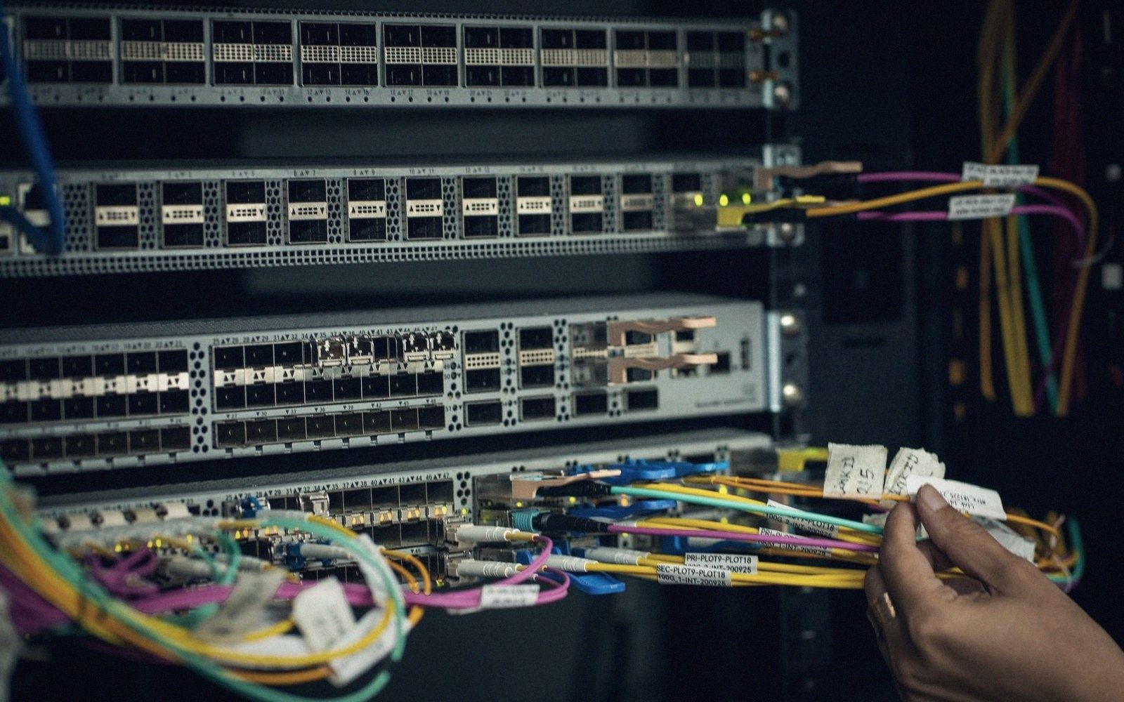
One fibre, many homes
A passive splitter divides light with no power and no active parts, which is why the architecture is cheap to run and awkward to change.

01How a splitter works
Pull a single-mode fibre into a fused biconical taper — twist two cores together, heat them, draw them — and optical power redistributes across both outputs. Do that in a cascade, or etch a planar lightwave circuit onto a silica chip, and you can fan one input into 2, 4, 8, 16, 32 or 64 outputs. No electronics, no power supply, no firmware. The device sits in a closure for decades without anyone visiting it. That is the splitter's core appeal: there is genuinely nothing to fail.
The loss is the trade-off. Every split halves the optical power, so each doubling costs roughly 3.5 dB — plus a small excess loss from the coupler itself. A 1:32 split burns around 17–18 dB before the signal has left the distribution network. An optical line terminal at the headend and an optical network unit at the premises must both operate within a power budget — typically 28 dB on a standard GPON link, somewhat more on XGS-PON — that has to accommodate fibre attenuation, connector losses and the splitter's share all at once. Push the split ratio too high, extend the reach, or add a second splitter stage and the budget evaporates faster than expected.
02Architecture choices
Most deployments choose between a single-stage and a two-stage split. Single-stage places a 1:32 or 1:64 cassette in a cabinet or a large closure close to the headend and runs individual fibres all the way to the premise. The headend fibre count is small; the distribution fibre count is large. Two-stage puts a 1:4 or 1:8 splitter at the street cabinet, then a second 1:8 or 1:4 at a smaller distribution point closer to the cluster of homes. The first feeder fibre is now shared across the middle mile, which can reduce duct occupancy on the congested route out of the exchange — but adds another passive node in the ground, another closure to seal and another point where someone can introduce a fault during a later dig.
Where a deployment zone has uneven density, two-stage architecture lets the second splitter be placed and sized for each sub-cluster independently. A terrace of eight houses gets a 1:8; a cul-de-sac of four gets a 1:4. In practice, network planners often standardise on one cassette size for inventory simplicity and accept some stranded capacity at the thinner ends of the topology.
The splitter location also determines how the network behaves when a customer leaves and another arrives. Every premises served by a given splitter shares the downstream wavelength broadcast from the OLT. The OLT identifies each ONT by a unique serial number during ranging, and the ONT decrypts only the frames addressed to it — but physically, the light is going everywhere on that branch. A new customer appearing at port 17 of a 1:32 does not require a truck roll to the splitter; they appear automatically once their ONT is powered and registered. That is the activation simplicity that made PON architectures attractive to operators running large-scale roll-outs.
03What it costs to change
The passive splitter's durability is real. What is harder to change is the split ratio itself. Once a 1:32 cassette is in a sealed closure and serving live customers, changing the ratio, for example to reduce contention by moving to 1:16, means a physical visit, a new cassette, re-routing of pigtails, and a maintenance window. The upstream feeder fibre stays the same; it is the distribution that has to be re-engineered.
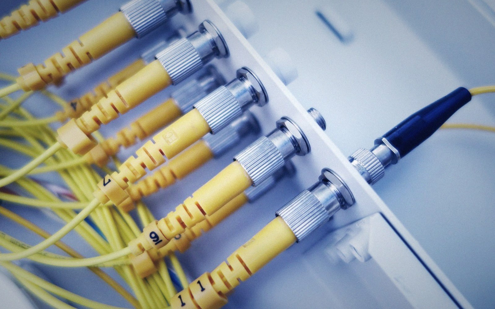
Operators who anticipate future wavelength stacking — running GPON and XGS-PON simultaneously on separate wavelengths through the same splitter — should confirm that the chosen cassette is wavelength-flat across the relevant window. A splitter optimised for 1,310/1,490/1,550 nm will still pass 1,577 nm used by XGS-PON downstream, but verifying insertion loss at that wavelength before the glass is buried is considerably cheaper than discovering a problem afterwards.
The passive splitter is not glamorous. It is a small chip or a knot of fused glass sitting in a plastic cassette inside an enclosure, never touched for the life of the network. What it does is distribute light cheaply, reliably, and without question — as long as the budget was designed correctly in the first place.
Key numbers
- 1:2 split — approximately 3.5 dB loss per stage (theoretical 3.0 dB plus excess loss)
- 1:32 split — approximately 17–18 dB total insertion loss
- 1:64 split — approximately 21–22 dB total insertion loss
- Standard GPON power budget — approximately 28 dB (Class B+)
- XGS-PON extended reach budgets — up to Class C+ and beyond, enabling longer reach or higher split ratios

| Single-stage split | lower passive node count, higher distribution fibre count, simpler to fault-find |
| Two-stage split | shares feeder fibre across middle mile, suits variable-density zones, adds a second closable point of failure |
| Wavelength stacking | verify cassette insertion loss across all operating wavelengths before installation; do not assume a PON splitter is flat at 1,577 nm |